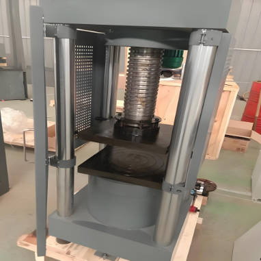
Gear Bending Fatigue Testing Service – Accredited Evaluation of Tooth Root Strength and Endurance Under Cyclic Bending Loads
For Belgian manufacturers, gear designers, and quality engineers in the automotive, wind energy, aerospace, marine, and heavy machinery sectors, the bending fatigue strength of gear teeth is a fundamental parameter that determines the reliability, service life, and safety of gear drives. Gear teeth are repeatedly subjected to bending stresses at the root during meshing, and over time, these cyclic stresses can lead to crack initiation and catastrophic tooth fracture. Our ISO/IEC 17025 accredited laboratory offers a specialised gear bending fatigue testing service that precisely measures the endurance limit and the S‑N curve (stress‑life) of gear teeth under controlled pulsating or reversing bending loads. Using purpose‑built pulsator testing machines, strain‑gauged test gears, and high‑speed data acquisition, we quantify the tooth root stress at failure and the number of cycles to failure, providing the essential data for gear design optimisation, material selection, and quality control. With our BELAC accreditation, our test reports are recognised by the Belgian Federal Public Service (FOD Economie), notified bodies, and authorities under the Machinery Directive (2006/42/EC), the Construction Products Regulation (EU 305/2011), and the relevant harmonised standards (ISO 6336, AGMA 2101, DIN 3990, etc.).
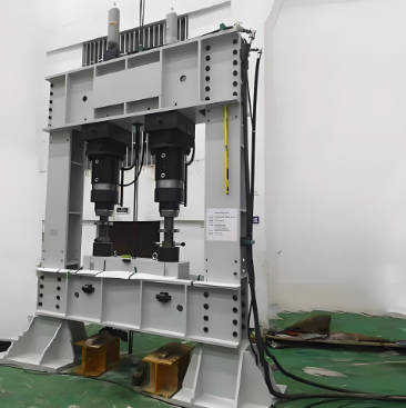
Gear Types and Specimens We Regularly Test
We accept a wide range of gear types and sizes, from small instrument gears to large industrial gear wheels. Our pulsator test rigs accommodate spur, helical, bevel, and worm gears, as well as specially prepared test coupons cut from gear rims. Common samples include:
- Spur and helical gears – for automotive transmissions, industrial gearboxes, and wind turbine drives.
- Bevel and hypoid gears – for differentials and right‑angle drives.
- Planetary gears and sun gears – for epicyclic gear trains.
- Test specimens cut from gear rims (single‑tooth bending test pieces) – for material characterisation and heat‑treatment validation.
- Gears with different heat treatments – carburised, nitrided, induction‑hardened, and through‑hardened.
- Gears with different materials – alloy steels (e.g., 18CrNiMo7‑6, 16MnCr5), case‑hardening steels, and sintered metals.
- Gears with different tooth geometries – standard, high‑transverse‑contact‑ratio, and modified root profiles.
- Gears after service or accelerated wear – to assess remaining fatigue life.
Core Test Methods – Pulsator, Resonant, and Single‑Tooth Bending Fatigue
Our gear bending fatigue testing service employs several standardised test methods, each designed to evaluate the bending fatigue strength of the tooth root under realistic loading conditions. The choice of method depends on the gear size, the available quantity of test gears, and the desired test accuracy:
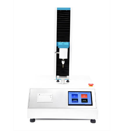
- Constant‑amplitude pulsator test – according to ISO 6336‑5 (gear rating – strength and quality of materials), AGMA 2101, and DIN 3990 – We mount a test gear on a pulsator test rig that applies a pulsating bending load to a single tooth (or to a pair of teeth) at a controlled frequency (typically 5‑30 Hz) and a defined load amplitude. The load is applied through a hardened roller (or a mating gear tooth) that simulates the meshing contact. The number of cycles to tooth fracture (or to the initiation of a visible crack) is recorded. The test is performed at multiple load levels to generate the S‑N curve (stress vs. cycles) for the gear material. We use strain gauges on the tooth root to calibrate the applied load to the actual bending stress.
- Resonant fatigue test (vibratory) – for rapid screening of many specimens, particularly for small gears or coupon‑type specimens – We mount a pre‑notched or standard tooth specimen on an electrodynamic shaker (or a resonant fatigue machine) and excite it at its natural frequency, creating a high‑cycle‑fatigue environment at a high frequency (up to 200 Hz). The test is performed at a defined stress amplitude (controlled by the excitation force). This method is particularly useful for generating the high‑cycle portion of the S‑N curve (above 10⁶ cycles).
- Single‑tooth bending test (STB) – according to ISO 6336‑5 (annex B), ASTM E1487, and FZG (Forschungsstelle für Zahnräder und Getriebebau) procedures – We cut a single tooth from the gear rim and fix it in a special holder. A cyclic bending load is applied directly to the tooth tip, simulating the bending stress at the root. This test allows precise control of the stress amplitude and is especially useful for testing small‑batch or prototype gears, or for comparing different materials and heat treatments without needing a large gear quantity.
- Run‑to‑failure and step‑load testing – to determine the endurance limit and the fatigue strength at a given number of cycles – In the run‑to‑failure approach, we test specimens at a fixed stress level until fracture. In the step‑load approach, we increase the load incrementally (e.g., every 10⁵ cycles) until failure, allowing the rapid determination of the endurance limit.
- Load‑strain calibration – we apply strain gauges to the tooth root of a representative gear and measure the strain at defined load levels, converting the strain to bending stress using the material's elastic modulus and Poisson's ratio – This calibration is used to convert the applied load into bending stress, which is necessary for generating the S‑N curve and for comparing results with design standards.
Specimen Preparation and Instrumentation
Proper specimen preparation and instrumentation are essential for accurate and repeatable fatigue test results. We follow strict procedures to minimise variability:
- Tooth preparation – we clean and degrease the test gears, and we inspect them for any surface defects, grinding burns, or tool marks that could act as stress raisers – We use dye penetrant inspection and magnetic particle inspection to detect and eliminate specimens with pre‑existing cracks.
- Strain gauge application – we bond high‑quality strain gauges (typically 350 Ω, with a gauge length of 1‑3 mm) at the tooth root radius, following a defined orientation (tangential to the root fillet) and using a strain gauge adhesive that is compatible with the gear material and the test environment – We use a Wheatstone bridge circuit with temperature compensation and calibrate the strain measurement using a known bending load.
- Measurement of tooth geometry – we measure the tooth root radius, the module, the pressure angle, and the tooth thickness using a coordinate measuring machine (CMM) or a profilometer – These parameters are used to calculate the stress concentration factor and the nominal bending stress.
- Mounting and alignment – we carefully align the test gear in the pulsator or resonant machine to ensure that the load is applied uniformly across the tooth face and that no additional bending moments are introduced – We use precision fixtures and dial gauges to achieve alignment within < 0.05 mm.
- Surface condition – we check the surface roughness (Ra) of the tooth root and the grinding marks, as a smoother surface generally improves the fatigue strength – We measure the surface roughness and note any deviations from the specification.
Environmental and Operational Conditioning – Simulating Service Conditions
Gear bending fatigue strength is influenced by temperature, lubrication, and the presence of corrosive media. We offer conditioning options to match your actual operating environment:
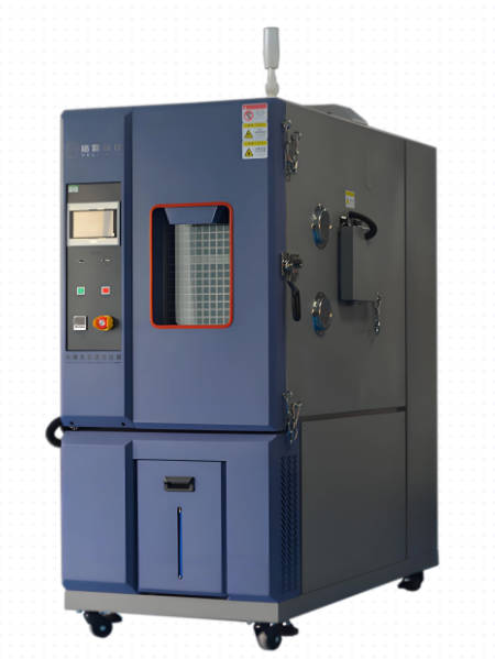
- Temperature‑conditioned fatigue testing – at elevated (up to 150°C) or low (down to -40°C) temperatures – using an environmental chamber on the test rig – We perform the fatigue test at the target temperature to evaluate the effect of temperature on the yield strength, the strain‑hardening behaviour, and the fatigue life.
- Lubricated testing – we perform the fatigue test with a continuous flow of the actual gear oil (or a simulant) to simulate the real service condition and to study the effect of lubrication on fatigue (e.g., the influence of oil viscosity and anti‑wear additives) – We use an oil circulation system with temperature control.
- Corrosion‑conditioned testing – we pre‑expose the gear to salt spray (ASTM B117) or a corrosive atmosphere, and then perform the fatigue test to assess the effect of corrosion pits or surface roughening on the fatigue life – This is particularly relevant for offshore and marine applications.
- Pre‑conditioning with overload cycles – we apply a small number of cycles at a higher load (e.g., 120% of the expected fatigue limit) to introduce a residual compressive stress at the root, which can improve the fatigue life (the so‑called “coaxing” effect) – We provide a comparison of the fatigue life with and without pre‑conditioning.
Data Analysis and S‑N Curve Generation
From the test results, we generate the S‑N curve (or Wöhler curve), which is the fundamental design tool for fatigue‑loaded gear teeth. Our analysis includes:
- Plotting of the stress amplitude (S) versus the number of cycles to failure (N) – we fit the data using a power‑law relationship (Basquin equation: S = a·N^b) or the staircase method for the endurance limit – We provide the equation of the fitted curve and the statistical parameters.
- Determination of the endurance limit (fatigue limit) – the stress amplitude below which the gear tooth can withstand an infinite number of cycles (typically 10⁶ or 10⁷ cycles) – We use the staircase method (according to ISO 12107) to determine the endurance limit with statistical confidence.
- Statistical analysis – we calculate the mean, standard deviation, and confidence intervals for the fatigue life at each stress level, and we determine the scatter of the results – This is important for probabilistic design.
- Comparison with design standards – we compare the measured fatigue strength (e.g., the bending stress at 10⁶ cycles) with the allowable bending stress values given in ISO 6336, AGMA 2101, or other design codes – We provide a direct comparison and an assessment of the safety margin.
- Fractographic analysis – after the test, we examine the fracture surface of the tooth to determine the initiation point (typically at the root radius) and to identify any inclusions, grinding burns, or other defects that may have caused premature failure – We use optical microscopy and, if needed, scanning electron microscopy (SEM) for detailed analysis.
Calibration, Accuracy, and Quality Assurance
All gear bending fatigue tests are performed under our ISO/IEC 17025:2017 accredited quality system, with full traceability of force, strain, frequency, and temperature measurements:
- Calibration of the pulsator load cell – according to ISO 7500‑1, ASTM E74, and EN ISO 7500‑1 – We calibrate the load cell using a certified reference load cell, achieving an uncertainty < 0.5% of the applied load.
- Calibration of strain gauges – using a calibrated strain indicator and a known bending moment (e.g., a four‑point bending fixture) – We verify the strain measurement with a known strain standard.
- Calibration of the displacement and frequency sensors – using a calibrated tachometer and a frequency counter – We verify the rotational speed and the cycle frequency with an uncertainty < 0.1%.
- Verification with reference gears – we test a reference gear with known fatigue properties at regular intervals to confirm the stability of the test system – The results are tracked on control charts.
- Interlaboratory comparison (ILC) – we participate in proficiency testing schemes for gear fatigue and material testing – Our results are regularly compared with those of other accredited laboratories.
Compliance with Belgian and European Regulations
Our gear bending fatigue testing services support your conformity assessment under the relevant European directives and Belgian regulations for machinery, pressure equipment, and structural components:
- Machinery Directive (2006/42/EC) – for gearboxes, drives, and lifting equipment – The bending fatigue strength is a critical parameter for verifying the safety and reliability of gear transmissions.
- Construction Products Regulation (CPR, EU 305/2011) – for gear drives in wind turbines, cranes, and hoists – The fatigue life of gears is a key performance parameter for the Declaration of Performance (DoP).
- Pressure Equipment Directive (PED 2014/68/EU) – for gears in pressurised fluid systems (e.g., hydraulic pumps) – The reliability of gears under cyclic loading is part of the safety assessment.
- Belgian workplace safety (ARAB) – for lifting and hoisting equipment – Our reports are used to verify that the gear drives meet the required safety margins.
Reporting and Accreditation
All tests are performed under our ISO/IEC 17025:2017 accredited quality system, with full traceability of all measurement parameters. Our BELAC‑accredited reports are recognised by the FOD Economie, Belgian notified bodies, and European authorities. Each report includes:
- A complete description of the test gear (material, heat treatment, geometry, surface finish).
- The test method and conditions (load type, frequency, temperature, lubrication).
- The S‑N curve (graphical and tabulated data) with the fitted Basquin equation.
- The endurance limit (fatigue limit) and the statistical confidence interval.
- Strain gauge calibration data and load‑stress correlation.
- Fractographic images of the fracture surface and an analysis of the failure initiation point.
- Calibration certificates and measurement uncertainty statements.
- A professional conclusion on the bending fatigue strength of the gear and its suitability for the intended application, with recommendations for design or process improvement if necessary.
Our reports provide the confidence you need to certify your gear products, approve deliveries, and ensure the safe and reliable operation of your machinery.
Why Choose Our Gear Bending Fatigue Testing Service?
We understand that gear tooth fracture is one of the most common and catastrophic failure modes in power transmission systems. Our testing service provides the precise, design‑ready data you need to validate your gear designs, select the right material and heat treatment, and ensure compliance with safety standards. We offer rapid scheduling, flexible test programmes (from single‑load screening to comprehensive multi‑level S‑N curve generation), and clear, engineering‑focused interpretation – we do not simply give you a fatigue life number; we explain the physical mechanisms behind the failure, the influence of tooth geometry and surface condition, and the practical steps you can take to improve fatigue performance. We work closely with your gear designers, materials engineers, and quality managers to design a test programme that matches your specific gear application and regulatory requirements. With state‑of‑the‑art pulsators, resonant machines, environmental chambers, and a highly experienced team, our gear bending fatigue testing service delivers the accuracy, repeatability, and regulatory acceptance you need to ensure that your gears can withstand the cyclic bending loads of real‑world service in the Belgian and European industrial landscape. Contact us to discuss your gear types, loading conditions, and performance targets – we will develop a tailored test programme that provides the definitive assessment of your gear's bending fatigue strength.