Vertical Destructive Load and Failure Load Testing Service – Accredited Ultimate Strength Assessment for Columns, Supports, and Structural Components
For Belgian structural engineers, manufacturers, construction companies, and quality managers in the civil, industrial, and infrastructure sectors, the accurate determination of the maximum vertical load that a structural element can sustain before failure is essential for safe design, regulatory compliance, and risk management. Our ISO/IEC 17025 accredited laboratory offers a specialised vertical destructive load and failure load testing service that precisely quantifies the ultimate compression, buckling, and crushing strength of columns, struts, supports, and other load‑bearing components. With decades of experience in structural testing and a comprehensive range of hydraulic test frames, we provide data that directly supports design validation, material qualification, and quality assurance. Our BELAC‑accredited reports are recognised by the Belgian Federal Public Service (FOD Economie), notified bodies, and all relevant authorities under the Construction Products Regulation (EU 305/2011), the Machinery Directive (2006/42/EC), and Eurocode standards (EN 1990‑1999).
Structural Components We Regularly Test
We accept a broad range of vertical load‑bearing elements, from small‑diameter struts and fasteners to large‑scale columns and support structures. Our hydraulic test frames, with capacities from 100 kN to 5,000 kN, accommodate specimens of varying lengths, cross‑sections, and materials. Common samples include:
- Steel and aluminium columns – I‑beams, H‑sections, hollow sections, and angle profiles.
- Concrete pillars and masonry columns – precast, cast‑in‑place, and reinforced concrete elements.
- Wood and glued‑laminated (glulam) columns – for residential and commercial timber construction.
- Composite columns – concrete‑filled steel tubes, fibre‑reinforced polymer (FRP) columns.
- Struts and braces – for scaffolding, temporary works, and formwork systems.
- Support posts and jacks – for structural shoring, mining, and tunnelling.
- Machine bases and equipment supports – for heavy industrial machinery.
- Fastening and anchoring systems – under vertical tension or compression loads.
Ultimate Compression Strength Test – Determination of Failure Load
The ultimate compression strength is the maximum axial load a specimen can withstand before it fails by crushing, buckling, or yielding. Our vertical destructive load and failure load testing follows the most recognised international and European standards, with Belgian NBN implementations, to provide the data required for structural design and verification:
- Axial compression test for metallic columns – ISO 6892‑2 (metals), ASTM E9, and NBN EN ISO 6892‑2 – We place a cylindrical or prismatic specimen between two parallel platens and apply a continuously increasing compressive load at a controlled rate (typically 0.5‑2 mm/min) until failure. We record the load‑displacement curve, determine the maximum load (F_max), and calculate the ultimate compressive strength (σ_ult = F_max / A₀, where A₀ is the original cross‑sectional area). The failure mode – crushing, barrelling, or shear fracture – is noted.
- Compression test for concrete and masonry – ISO 4012, ASTM C39, and NBN EN ISO 4012 (concrete cylinders or cubes); ASTM C1314 (masonry prisms) – We test concrete cylinders (150 mm × 300 mm) or cubes (150 mm) and masonry prisms (brick or block stacks) under axial compression at a specified loading rate (0.2‑0.4 MPa/s). The maximum load, the compressive strength (in MPa), and the failure pattern (e.g., cone‑shaped, crushing, splitting) are reported.
- Compression test for timber columns – ISO 13910, ASTM D143, and NBN EN ISO 13910 – We test small clear specimens or full‑sized structural members parallel to the grain. The compression strength parallel to the grain and the modulus of elasticity are determined, and the failure mode (crushing, splitting, or buckling) is recorded.
- Compression test for composite columns – ISO 8515, ASTM D695, and NBN EN ISO 8515 – For FRP and concrete‑filled steel tubes, we perform axial compression tests to determine the ultimate load and the interaction between the steel shell and the concrete core. Strain gauges are applied to measure the axial and circumferential strains, allowing calculation of Poisson's ratio and the confinement effect.
- Buckling test – to determine the critical buckling load for slender columns (Euler buckling) – For long, slender columns, we apply a gradually increasing axial load until the column deflects laterally and collapses. We record the load at which buckling occurs, the lateral deflection, and the post‑buckling behaviour. The test is performed with different end conditions (pinned‑pinned, fixed‑fixed, fixed‑pinned) to match the actual support conditions.
Failure Load Under Eccentric and Combined Loading
In practice, many columns are subjected to eccentric loads or combined axial and bending forces, which reduce the ultimate capacity. Our laboratory offers specialised test setups to simulate these realistic loading conditions:
- Eccentric compression test – ISO 8632, ASTM E111, and EN 1993‑1‑1 (Eurocode) – We apply the axial load with a controlled eccentricity by using a load‑application point offset from the column centreline. The eccentricity (e) is set to a defined value (e.g., 10 mm, 25 mm, or 50 mm) and the column is loaded until failure. We measure both the axial deformation and the lateral deflection to determine the load‑moment interaction and the reduction in ultimate load compared to concentric loading.
- Combined compression and bending test – to simulate column behaviour in moment‑resisting frames – We apply a constant axial load (e.g., 30% of the concentric ultimate load) and gradually increase a lateral bending moment (by a point load at mid‑span or by a three‑point bending arrangement) until failure. The interaction curve (axial load vs. bending moment) is plotted, which is essential for the design of columns in seismic areas.
- Combined compression and torsion test – for columns subject to torsional moments (e.g., from out‑of‑plane loading) – We apply a constant axial load and a monotonic or cyclic torsional moment, measuring the angle of twist and the axial shortening. The combined failure load is determined for use in the design of columns in complex structures.
- Load history and unloading‑reloading cycles – to determine the residual strength after a partial overload – We load the column to a certain fraction of the ultimate load (e.g., 70%), unload, and then reload to failure. This test simulates the effect of accidental overloads and provides information on the degradation of stiffness and strength.
Strain and Deformation Monitoring – Data Acquisition for Engineering Analysis
Beyond the failure load, we provide comprehensive strain and deformation data that supports finite‑element model validation and detailed structural analysis:
- Axial displacement measurement – using LVDTs and dial gauges positioned on the test frame and directly on the specimen – We measure the shortening of the column under load, plotting the load‑shortening curve. The modulus of elasticity (E) is derived from the initial linear portion of the curve.
- Lateral deflection measurement – for buckling studies – using multiple LVDTs or laser displacement sensors at several heights – We record the lateral deflection along the column length to determine the buckled shape and to compare with theoretical predictions.
- Strain gauge application – uniaxial and rosette strain gauges are bonded to the surface of the column to measure local strains (ISO 9513, ASTM E251) – We use strain gauges on both the compression and tension faces (for bending) to capture the strain distribution and to detect the onset of local yielding or crushing.
- Digital image correlation (DIC) – for full‑field strain mapping and visualisation of deformation patterns – On request, we use high‑resolution cameras and DIC software to capture the displacement and strain fields over the entire column surface. This is particularly useful for understanding the localised yielding or buckling mechanisms and for validating numerical models.
- Data logging and real‑time monitoring – all sensors are connected to a high‑speed data acquisition system that records load, displacement, and strain at rates up to 1000 Hz – This ensures accurate capture of the failure event and allows for post‑test analysis of the failure sequence.
Failure Mode Classification and Post‑Test Examination
Understanding the failure mode is as important as the ultimate load itself. We provide a detailed analysis of the failure mechanism to support design optimisation and forensic investigation:
- Visual classification – based on the observed behaviour: crushing, barrelling, shear fracture, local buckling, Euler buckling, or torsional buckling – We document the failure pattern with high‑resolution photographs and provide a description of the failure sequence.
- Measurement of permanent deformation – we measure the residual length, diameter, and any out‑of‑straightness after the test – The permanent set provides an indication of the ductility of the material and the energy absorbed during failure.
- Metallographic examination (for metals) – we prepare cross‑sections of the failure zone and examine the grain structure, the presence of voids, and any evidence of crack initiation (ASTM E3, E112) – This helps differentiate between ductile and brittle failure mechanisms and may reveal material defects.
- Microscopic examination (for concrete and masonry) – we inspect the fracture surfaces for aggregate fracture, mortar cracking, and bond failure – The type of failure (e.g., through the aggregate, through the mortar, or at the interface) indicates the quality of the materials and the construction technique.
- Correlation with analytical predictions – we compare the measured ultimate load, buckling load, and deflection with calculations based on Eurocode, AISC, or other design codes – This provides a direct validation of the design models and helps identify over‑ or under‑design.
Environmental Conditioning and Long‑Term Behaviour
For elements that may be exposed to environmental extremes or long‑term loads, we offer conditioning before the destructive test:
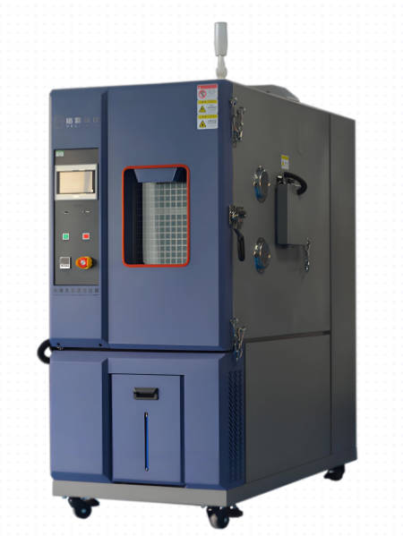
- Temperature conditioning – at elevated (up to 300°C) or low (down to -40°C) temperatures, in a thermal chamber – We perform the compression test after stabilising the specimen at the target temperature to measure the effect of temperature on the ultimate load.
- Humidity and moisture conditioning (ASTM D618, ISO 291) – for timber and hygroscopic materials – We condition specimens to a specified equilibrium moisture content (e.g., 12%, 18%, or 25%) and test them to determine the reduction in strength due to moisture.
- Creep and sustained load preconditioning – to evaluate the effect of long‑term loading on the residual capacity – We apply a constant load (typically 40‑60% of the estimated ultimate load) for a period of up to 1,000 hours, then unload and test to failure to measure the reduction in ultimate capacity caused by creep damage.
- Fire exposure preconditioning – for elements designed to fire‑resistant classes (ISO 834, EN 1363) – For columns that are part of fire‑resistant structures, we expose them to a standard fire curve (e.g., 60, 90, or 120 minutes) in a special furnace, then cool them and perform the compression test to assess the residual load‑bearing capacity.
Test Fixtures, Safety, and Calibration
All tests are performed in a safe, controlled environment with robust fixturing and calibrated instrumentation:
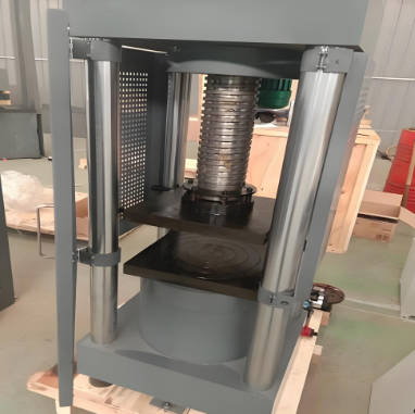
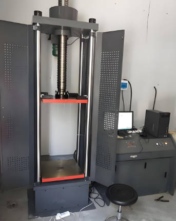
- Hydraulic compression frames with capacities up to 5,000 kN – equipped with precision load cells (class 0.5) and displacement transducers – The frames are maintained and calibrated according to ISO 7500‑1 and ASTM E74, with traceability to national standards. Measurement uncertainty is < 0.5% for load and < 0.1 mm for displacement.
- Spherical seats and parallel platens – to ensure uniform load distribution and prevent eccentricity – We use self‑aligning compression platens that automatically adjust to the specimen end surfaces, minimising any unintended bending moments.
- Safety cages and containment shields – to protect operators in the event of explosive failure – All high‑load tests are performed within safety enclosures, with remote control and observation.
- Regular calibration checks – we perform daily verification of the load cell using a certified reference load cell, and we run a full calibration annually – This ensures that the load and displacement readings are consistently accurate.
- Interlaboratory comparison (ILC) – we participate in proficiency testing programmes for compression testing of structural materials – Our results are regularly compared with those of other accredited laboratories to validate our procedures.
Compliance with Belgian and European Regulations
Our vertical destructive load and failure load testing services support conformity assessments under the key European directives and Belgian regulations for construction and structural safety:
- Construction Products Regulation (CPR, EU 305/2011) – The ultimate load and failure load data are essential parameters for the Declaration of Performance (DoP) of structural steel, concrete, timber, and composite elements. Our tests are carried out in accordance with the harmonised standards (e.g., EN 1993, EN 1994, EN 1995).
- Machinery Directive (2006/42/EC) – For lifting equipment, crane columns, and support structures that are subject to high vertical loads, we provide the structural verification data required for the risk assessment and CE marking.
- Eurocodes (EN 1990‑1999) – Our test results are directly used for the validation of design resistances, the calibration of partial safety factors, and the verification of structural stability in accordance with the Eurocodes.
- Belgian building regulations and ARAB – For temporary structures (scaffolding, formwork) and permanent installations, our reports are accepted by public authorities and workplace inspectors.
- REACH Regulation (EC 1907/2006) – For materials that contain substances subject to REACH, the test data on mechanical integrity under load is part of the safety and environmental assessment.
Reporting and Accreditation
All tests are performed under our ISO/IEC 17025:2017 accredited system, recognised by the FOD Economie and Belgian notified bodies. Each report includes:
- A detailed description of the test specimen (dimensions, material, preparation).
- Test conditions (load rate, end conditions, temperature, humidity).
- Load‑displacement and load‑strain curves (graphical and tabulated data).
- The ultimate failure load (F_max) and the corresponding compressive strength (σ_ult).
- Failure mode classification and photographic documentation.
- Comparison with design values and applicable standards.
- Measurement uncertainty and calibration records.
- A professional conclusion on the load‑bearing capacity and suitability for the intended application.
Our reports provide you with the confidence to certify your structural elements, approve deliveries, and satisfy regulatory requirements.
Why Choose Our Vertical Destructive Load and Failure Load Testing Service?
We understand that the failure load is the ultimate limit state that governs the safety of structures, and that accurate, reliable testing is essential to protect lives and assets. Our team offers rapid scheduling, flexible test configurations (from small struts to full‑scale columns), and clear, practical interpretation of results – we do not simply give you a failure load; we explain the implications for your design, provide recommendations for material or geometry improvements, and assist with your regulatory submissions. We work closely with your structural engineers, quality managers, and project teams to design a test programme that matches your specific loading conditions, support conditions, and applicable design codes. With high‑capacity hydraulic frames, precision instrumentation, and extensive engineering expertise, our vertical destructive load and failure load testing service delivers the precision, reliability, and regulatory acceptance you need to ensure safe, efficient, and compliant structures in the Belgian and European market. Contact us to discuss your structural components, load requirements, and certification goals – we will develop a tailored test plan that provides the definitive proof of your product's ultimate strength.